Mecanum wheels allow omnidirectional movement of the robot’s rolling base
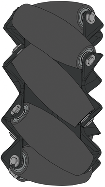
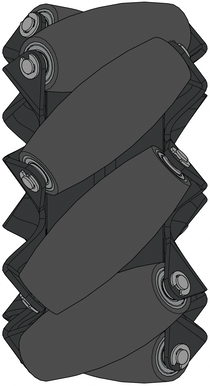
Each set of Mecanum wheels (REV-45-1655) is supplied with two right-hand Mecanum wheels (REV-41-1656) and two left-hand Mecanum wheels (REV-41-1657). This is determined by the direction of the leading edge of the rollers. If the rollers face left, it’s a left-hand wheel, and if they face right, it’s a right-hand wheel.
 |
 |
Each side of the chassis needs one left and one right wheel. Mecanum chassis also require four motors to operate.
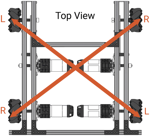
To check that your Mecanum wheels are correctly configured, look up and down the drive train. The diagonal lines created by the angle of the rollers should form an “X” as shown above.
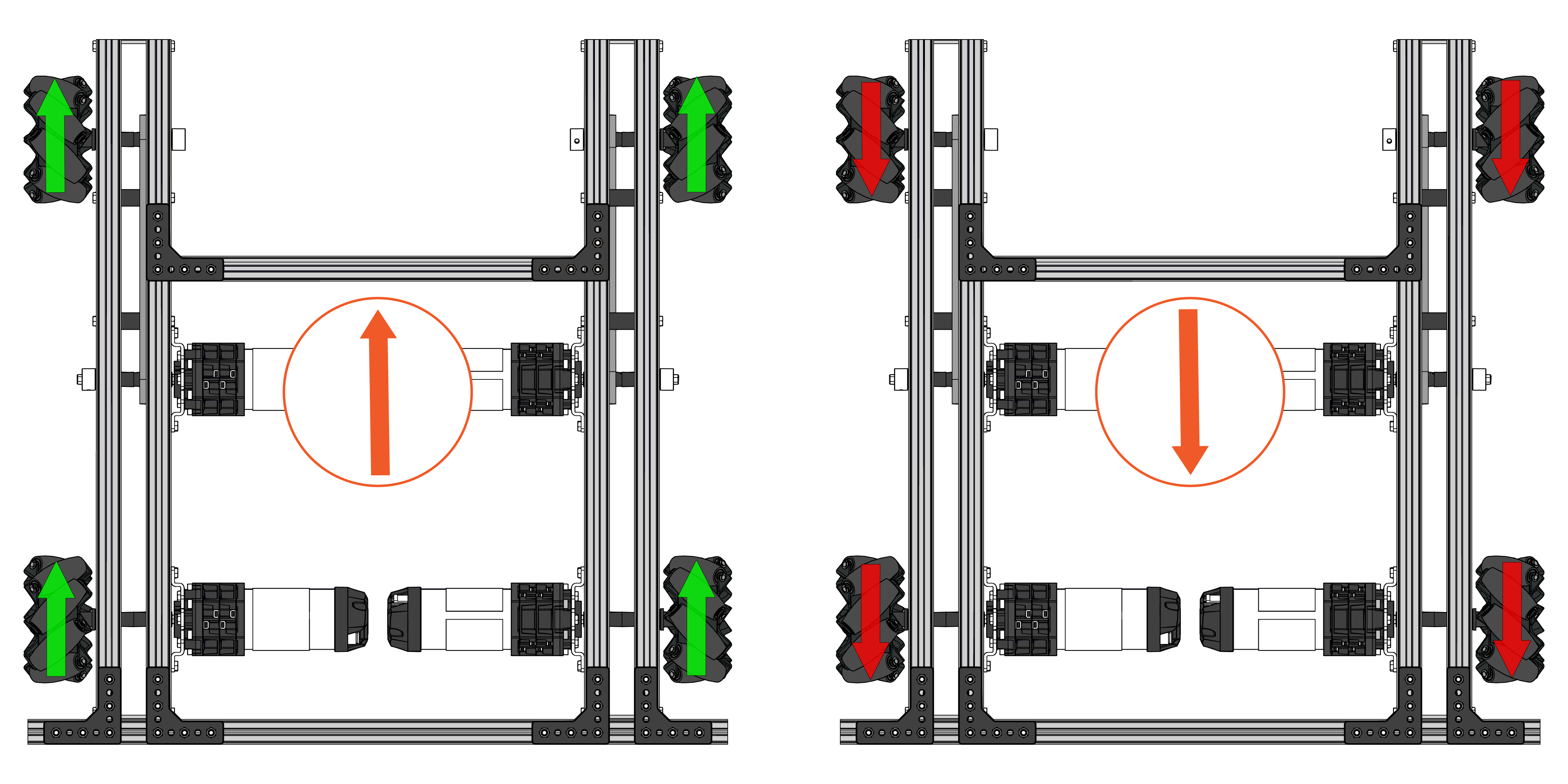
Mecanum wheel transmission behavior
Turning all four wheels in the same direction at the same speed results in forward/reverse motion, as longitudinal force vectors add up but transverse vectors cancel out, as shown in the diagram below.
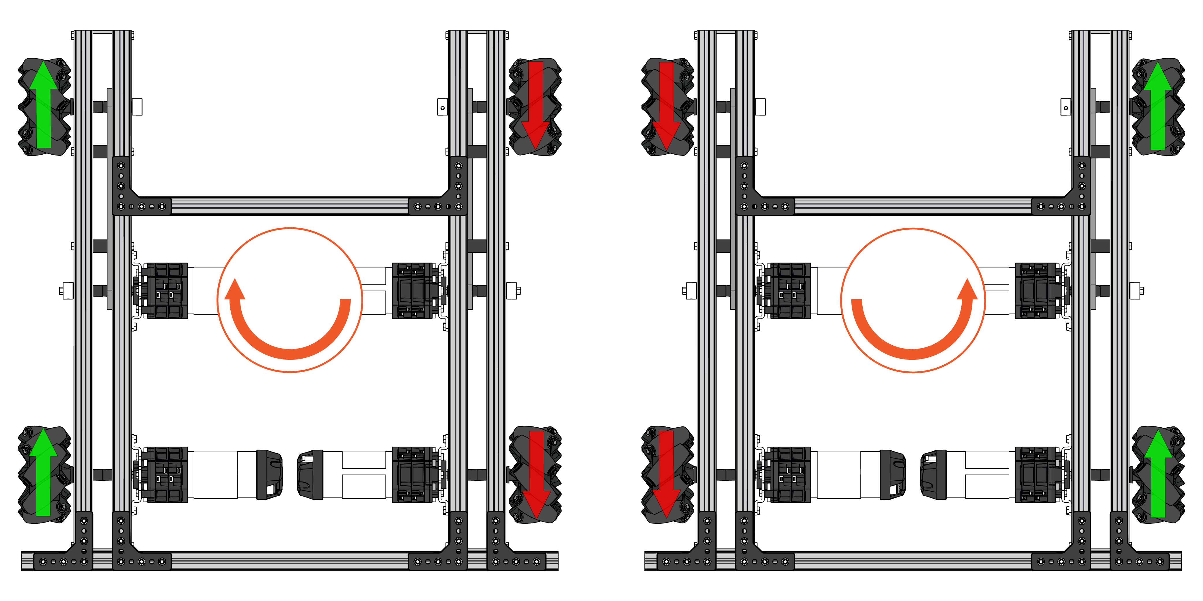
When both wheels on one side move in one direction while the other side moves in the opposite direction, the result is rotation around the transmission's central vertical axis, as illustrated below.
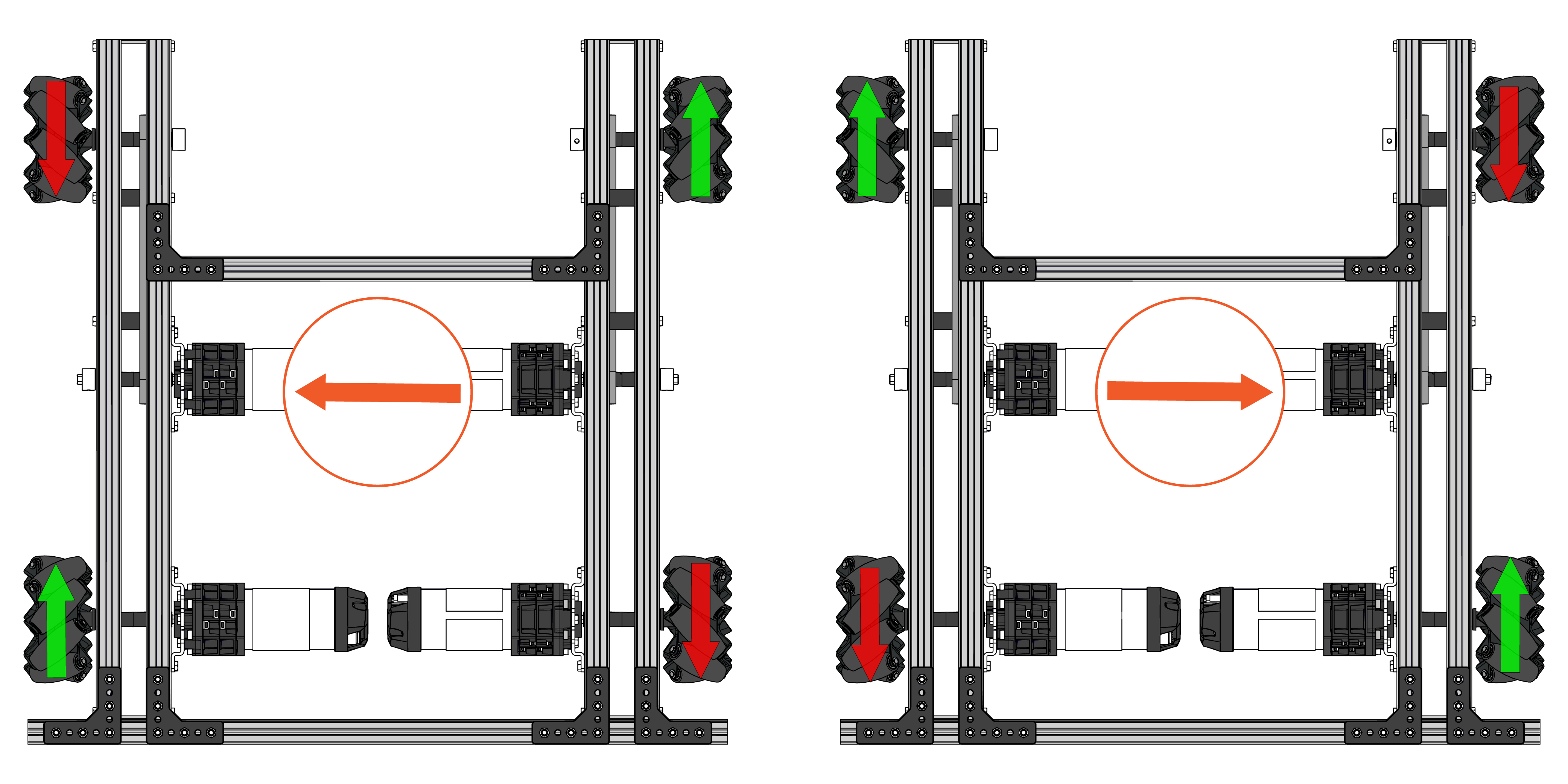
When the wheels on the right-hand mechanism turn in one direction, while the wheels on the left-hand mechanism turn in the opposite direction, the result is lateral movement.
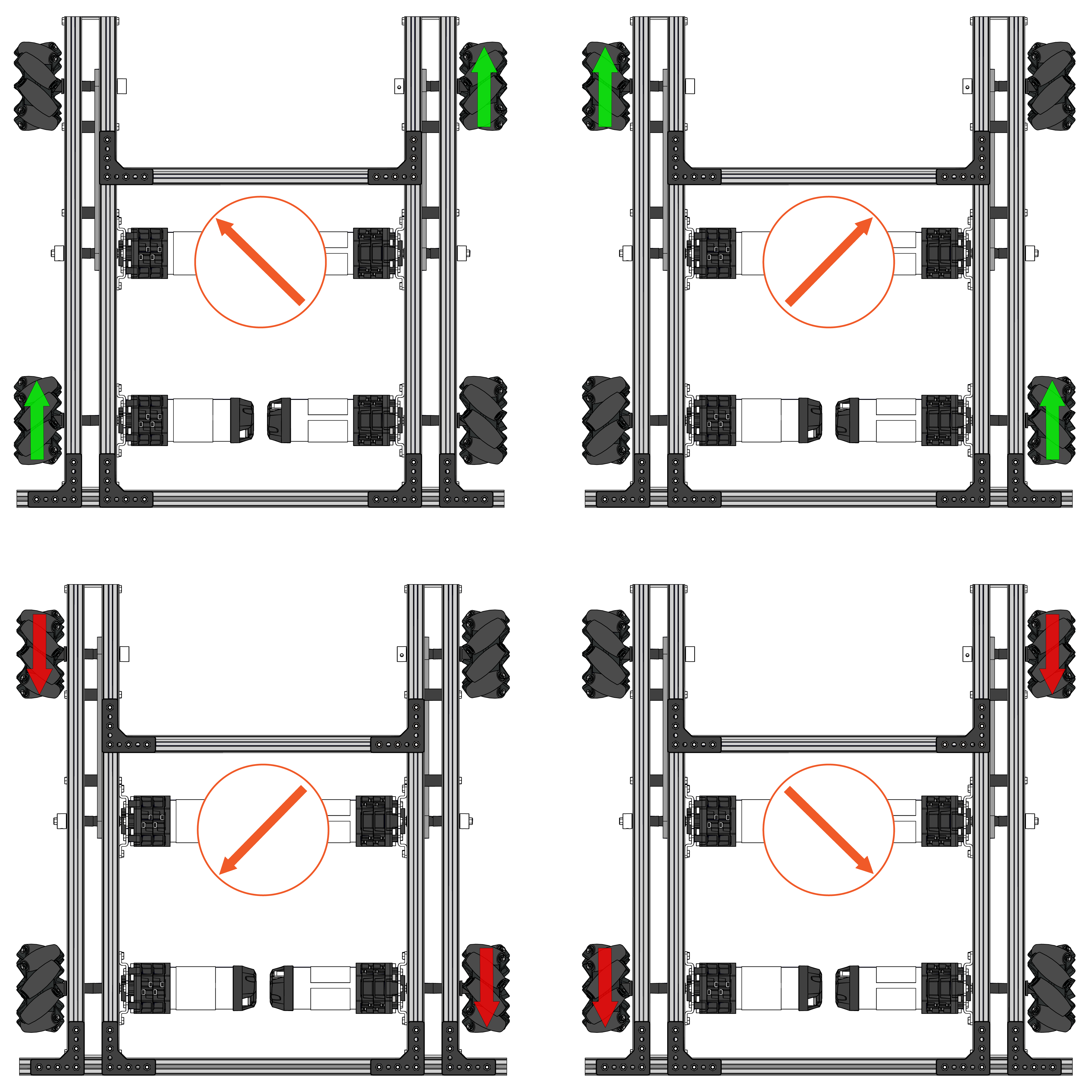
Using the above concepts in tandem, by varying the motor power for each type of wheel, enables the powertrain to move along different angular vectors.
Links to Java programming examples for beginners
There are two possible operator control modes:
- Robot-centric” mode, where the joystick controls the robot’s direction in relation to the robot chassis.
- Field-centric” mode, where the joystick controls the robot’s direction in relation to the operator’s field of vision.
Link : Mecanum TeleOp
Example of Java programming in stand-alone mode :
Link : Drivetrain Control